PIC buttons (polling)
Polling for button input, how useful! This is pretty brief and gives a good idea how to let buttons control your programs execution.
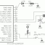
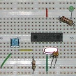
In this tutorial I’ve switched from using an oscillator to using a crystal. This changes the design a bit. Using the 2 OSC pins, OSC1/OSC2 (CLKOUT/CLKIN) they hook to the crystal in parallel. Then the two sides of the crystal are connected to ground via two capacitors, in this case 18pF. The speed and capacitance needed varies, and can be seen in most any PIC MCU datasheet as to how to lay it out. It will also be in my schematic.
Please note this is essentially NO DIFFERENT than the oscillator. It is simply a different means of providing a clock signal. You can swap in the oscillator to the normal CLKIN pin and it will work just fine.
For this program, we’ll start the processor, and wait for a button to be pressed. After it has been pressed we’ll essentially execute the LED blinker from before.
Polling is extremely simple. Polling is the act of checking something for a certain state to occur. In our case, we poll PORTB,4 waiting for it to go low. Once it does, we continue on and start blinking.
Another topic that needs to be covered is that of Pull-Up resistors. In order for a button to be able to change from 0 to 1 (Ground to 5V) we need a way to protect everything from a short circuit. We do this with a Pull-Up (or Pull-Down in some cases) resistor. For our case, we connect PORTB,4 to +5V via a 10k resistor. So when we fire up the program, the PIC sees PORTB,4 as HIGH. We then connect our button to PORTB,4 on one side, and Ground on the other. Now, when we press the button, PORTB,4 is connected to ground and is now LOW. A short circuit between +5 and Ground would occur if not for the resistor, which being 10k limits the current to a measly 500uA, nothing to worry about. Once the button is released, Ground is disconnected and the pin returns to a HIGH state.
Reading the code, you may also notice the _BANK macro has changed a bit. I’ve simply modified it to encompass all possible BANK configs instead of using 4 different macros for each. Reading through it can give you a little insight as to how the conditional assembler works. It’s a bit like C/C++ and a bit like BASIC. Quite nice and handy.
A final new bit is the _MCLRE_OFF in the __CONFIG line at the beginning. This frees us from having to pull _MCLR high to keep from a RESET condition. Just keeps our parts count down. 
Now for the new section of code.
btfsc PORTB,4 goto $-1 |
That’s polling, yup, that’s it. All it is doing is a bit test on PORTB,4, waiting for it to become clear (Ground). The goto line is telling it to go 1 instruction back ($ means the address of the current instruction, $-1 means one before, the btfsc). Once that pin becomes 0 it skips the loop forcing it to check, and lets it continue on down to the blinker!
Downloads
- Source Code (zip)

